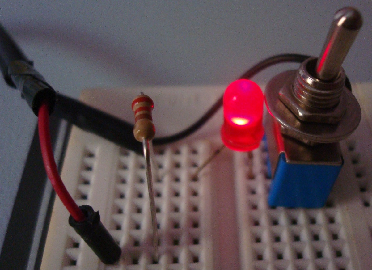
Finally I have been able to connect some hardware to my Pi.
I used the circuit published by adafruit, wiring 330 ohm resistors to the LEDs:

The original software was intended to change the active LED when a user received an e-mail. Since I intended to make something far simpler, I just changed the active LED every second.
Python:
In my first test, I wanted to use a tried-and-tested software in order to isolate an eventual problem. Therefore, I used the software provided by the adafruit tutorial. Since I don’t know how to program Python, I just removed the code I did not want.
#!/usr/bin/env python

import RPi.GPIO as GPIO, time

GPIO.setmode(GPIO.BCM)
 GREEN_LED = 18
 RED_LED = 23
 GPIO.setup(GREEN_LED, GPIO.OUT)
 GPIO.setup(RED_LED, GPIO.OUT)

while True:

GPIO.output(GREEN_LED, True)
 GPIO.output(RED_LED, False)

time.sleep(1)

GPIO.output(GREEN_LED, False)
 GPIO.output(RED_LED, True)

time.sleep(1)
C:
This is the language I have programmed for more years. I adapted the code from Gert van Loo & Dom in order to use only the GPIO pins connected to the LEDs.
//
// How to access GPIO registers from C-code on the Raspberry-Pi
// Example program
// 15-January-2012
// Original code from Dom and Gert (http://elinux.org/RPi_Low-level_peripherals#C)
// Revised: 15-Feb-2013
// Adapted by Wilson Medeiros (clockeater) on 30-Nov-2013
// Access from ARM Running Linux

#define BCM2708_PERI_BASE 0x20000000
#define GPIO_BASE (BCM2708_PERI_BASE + 0x200000) /* GPIO controller */
#include <stdio.h>
#include <stdlib.h>
#include <fcntl.h>
#include <sys/mman.h>
#include <unistd.h>

#define PAGE_SIZE (4*1024)
#define BLOCK_SIZE (4*1024)

int mem_fd;
void *gpio_map;

// I/O access
volatile unsigned *gpio;
// GPIO setup macros. Always use INP_GPIO(x) before using OUT_GPIO(x) or SET_GPIO_ALT(x,y)
#define INP_GPIO(g) *(gpio+((g)/10)) &= ~(7<<(((g)%10)*3))
#define OUT_GPIO(g) *(gpio+((g)/10)) |= (1<<(((g)%10)*3))
#define SET_GPIO_ALT(g,a) *(gpio+(((g)/10))) |= (((a)<=3?(a)+4:(a)==4?3:2)<<(((g)%10)*3))

#define GPIO_SET *(gpio+7) // sets bits which are 1 ignores bits which are 0
#define GPIO_CLR *(gpio+10) // clears bits which are 1 ignores bits which are 0

#define GPIO_GREEN_LED (18)
#define GPIO_RED_LED (23)

void setup_io();

int main(int argc, char **argv)
{
 int g,rep;

// Set up gpi pointer for direct register access
 setup_io();

// Switch GPIO 18 and 23 to output mode

/************************************************************************\
 * You are about to change the GPIO settings of your computer. *
 * Mess this up and it will stop working! *
 * It might be a good idea to 'sync' before running this program *
 * so at least you still have your code changes written to the SD-card! *
 \************************************************************************/

// Set GPIO pins 18 and 23 to output

INP_GPIO(GPIO_GREEN_LED); // must use INP_GPIO before we can use OUT_GPIO
 OUT_GPIO(GPIO_GREEN_LED);

INP_GPIO(GPIO_RED_LED); // must use INP_GPIO before we can use OUT_GPIO
 OUT_GPIO(GPIO_RED_LED);

for (rep=0; rep<10; rep++)
 {
 GPIO_SET = 1 << GPIO_GREEN_LED;
 sleep(1);
 GPIO_CLR = 1 << GPIO_GREEN_LED;
 GPIO_SET = 1 << GPIO_RED_LED;
 sleep(1);
 GPIO_CLR = 1 << GPIO_RED_LED;
 }

return 0;

} // main

//
// Set up a memory regions to access GPIO
//
void setup_io()
{
 /* open /dev/mem */
 if ((mem_fd = open("/dev/mem", O_RDWR|O_SYNC) ) < 0) {
 printf("can't open /dev/mem \n");
 exit(-1);
 }

/* mmap GPIO */
 gpio_map = mmap(
 NULL, //Any adddress in our space will do
 BLOCK_SIZE, //Map length
 PROT_READ|PROT_WRITE,// Enable reading & writting to mapped memory
 MAP_SHARED, //Shared with other processes
 mem_fd, //File to map
 GPIO_BASE //Offset to GPIO peripheral
 );

close(mem_fd); //No need to keep mem_fd open after mmap

if (gpio_map == MAP_FAILED) {
 printf("mmap error %d\n", (int)gpio_map);//errno also set!
 exit(-1);
 }

// Always use volatile pointer!
 gpio = (volatile unsigned *)gpio_map;
} // setup_io